PLCopen 2-Axes Template - FFLD and SFC
This template project contains a two-axis template for getting started with a KAS![]() Kollmorgen Automation Suite application.
Kollmorgen Automation Suite application.
- It contains key project elements that save development time.
- The templates are designed to add code to the programs
 The act of performing a sequence of instructions or commands. and Control Panels in the template or to new templates.
 - This template program can be run on the KAS Simulator or with an AKD PDMM or PCMM and AKD drives In electrical engineering, a drive is an electronic device to provide power to a motor or servo.
Control device for regulating the speed, torque and position of a motor.
A unit controlling a motor using the current and timing in its coils..
- This template program can be run on the KAS Simulator or with an AKD PDMM or PCMM and AKD drives
- A project can contain many programs, and each program can be written in FBD Function block diagram - Describes a function between input variables and output variables. A function is described as a set of elementary blocks., FFLD, IL Instruction list - This is a low-level language and resembles assembly., SFC Sequential function chart - It can be used to program processes that can be split into steps.
The main components of SFC are:
- Steps with associated actions.
- Transitions with associated logic conditions.
- Directed links between steps and transitions. or ST Structured text - A high-level language that is block structured and syntactically resembles Pascal. programming languages.
- Additional axes can be added to the template applications that have three, four, five, or more axes.
This project contains two axes where Axis 2 is slaved to Axis 1 at a 2:1 ratio.
PLC Programs
The 2-axes PLCopen![]() A vendor -and product- independent worldwide association active in Industrial Control and aiming at standardizing PLC file formats based on XML. template has an SFC program (called Main) that initializes and starts the motion.
A vendor -and product- independent worldwide association active in Industrial Control and aiming at standardizing PLC file formats based on XML. template has an SFC program (called Main) that initializes and starts the motion.
- The motion includes single axis jogging, incremental and absolute moves A positioning movement referenced to a fixed original position.
Example: If a stage is positioned at +500 mm, an absolute move to +300 mm would result in a move of 200 mm towards the origin (in the negative direction)., and gearing motion between axes.
- Controls are included to enable Enable signal for the drive, Hardware-Enable with 24V signal to X8, Software-Enable command by setup Software, fieldbus or permanently set.
Both are required for enabling the drive./disable Removal of the ENABLE signal.
Disables power stage. the drive, clear faults, and display fault and axis position Position means a point in space which is described by different coordinates.
Depending on the used system and transformation it can consist of a maximum of six dimensions (coordinates).This means three Cartesian coordinates in space and coordinates for the orientation.
In ACS there can be even more than six coordinates.
If the same position is described in different coordinate systems the values of the coordinates are different. information in the Control Panel.
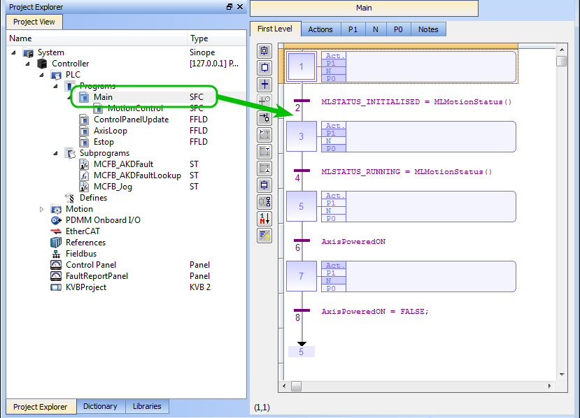
Figure 1: PLCopen - Template Main
Step 5 of the Main program in the PLCopen template contains the FFLD code for running the motion. As defined below with the MoveVelocity function block![]() A function block groups an algorithm and a set of private data.
It has inputs and outputs., the motion profile is based on a trapezoidal acceleration
A function block groups an algorithm and a set of private data.
It has inputs and outputs., the motion profile is based on a trapezoidal acceleration![]() A change in velocity over time.
Because velocity is a vector, it can change in two ways: a change in magnitude and/or a change in direction.
In one dimension, acceleration is the rate at which something speeds up or slows down.
However, more generally, acceleration is a vector quantity expressing the change with time of the velocity both in magnitude and in direction.
See these Wikipedia articles for more information:
http://en.wikipedia.org/wiki/Velocity
http://en.wikipedia.org/wiki/Euclidean_vector
http://en.wikipedia.org/wiki/Rate_(mathematics) / deceleration.
A change in velocity over time.
Because velocity is a vector, it can change in two ways: a change in magnitude and/or a change in direction.
In one dimension, acceleration is the rate at which something speeds up or slows down.
However, more generally, acceleration is a vector quantity expressing the change with time of the velocity both in magnitude and in direction.
See these Wikipedia articles for more information:
http://en.wikipedia.org/wiki/Velocity
http://en.wikipedia.org/wiki/Euclidean_vector
http://en.wikipedia.org/wiki/Rate_(mathematics) / deceleration.
See S-curve and Trapezoidal Acceleration / Deceleration.

Figure 2: PLCopen Template - Step 5 of the Main
The template contains two PLCopen Servo axes where User Units, Update Rate, Rollover Position, and Axis Limits are defined as:
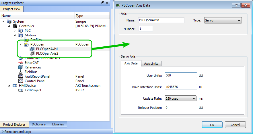
Figure 3: PLCopen Template - Motion
See Axis Data Parameters for more information about PLCopen axis parameters.
The template contains a Control Panel which works inside of the IDE![]() Integrated Development Environment - An type of computer software that assists computer programmers in developing software.
IDEs normally consist of a source code editor, a compiler and/or interpreter, build-automation tools, and a debugger. when running a project.
Integrated Development Environment - An type of computer software that assists computer programmers in developing software.
IDEs normally consist of a source code editor, a compiler and/or interpreter, build-automation tools, and a debugger. when running a project.
It is a useful tool to run and debug programs.
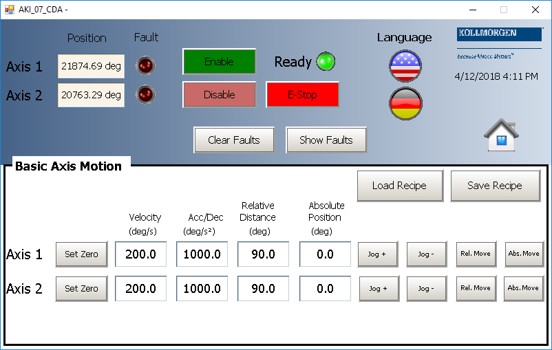
Control Panel Screens
The Control Panel has these screens:
- Control Panel
- Fault Report Panel
Control Panel Sections
The Control Panel has these sections:
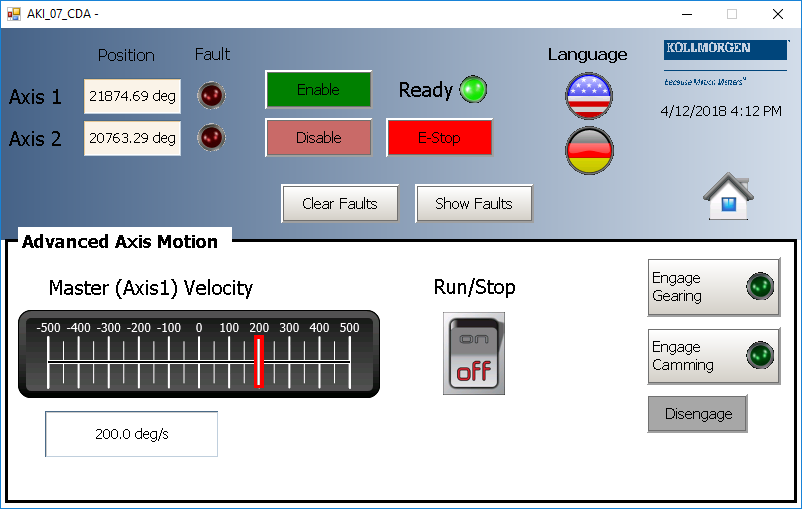
- Multi-Axis Commands: Controls motion and shows gearing.
- Single Axis Motion Commands: Shows motion at the single axis level and resetting New start of the microprocessor. the axis position.
- Axis Status: Shows basic axis information.
See Design the HMI with the Internal Editor for more information.
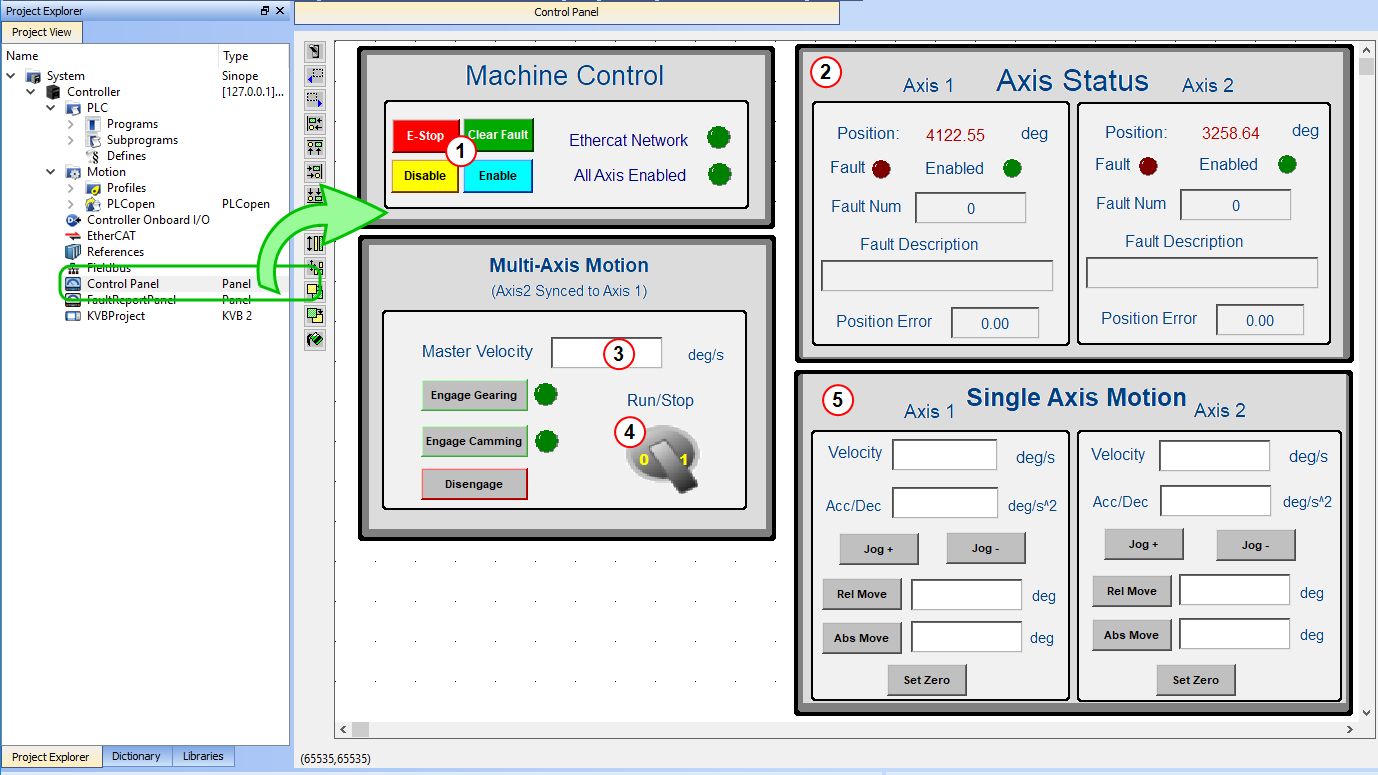
Figure 4: PLCopen Template - Control Panel
| Call out# | Description |
|---|---|

|
Allows for enabling or disabling the axes. After an emergency stop, select the Reset and Enable commands before running the axes. |

|
Displays the actual position for each axis. |

|
Used to set the speed |

|
Start or stop the motion on the condition that the axes are enable. The green light must be switched on. |

|
Control the axis motion. |
Fault Report Panel provides more detailed information about when a drive fault occurs.
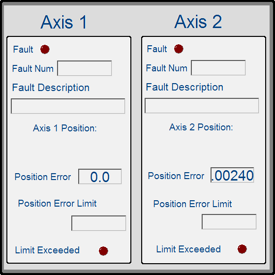
Figure 5: PLCopen Template - Fault Report Panel
Based on the template, the project can be run using either the:
- KAS Simulator Graphical User Interface.
- Actual drives and motors An actuator focused to a movement, converting electrical energy in a force or torque..
- In this case, set up the axes first in the EtherCAT Ethernet ofr Control Automation Technology.
EtherCAT® is an open, high-performance Ethernet-based fieldbus system.
The development goal of EtherCAT is to apply Ethernet to automation applications which require short data update times (also called cycle times) with low communication jitter (for synchronization purposes) and low hardware costs. part).
See Configuring EtherCAT for more information.
- In this case, set up the axes first in the EtherCAT
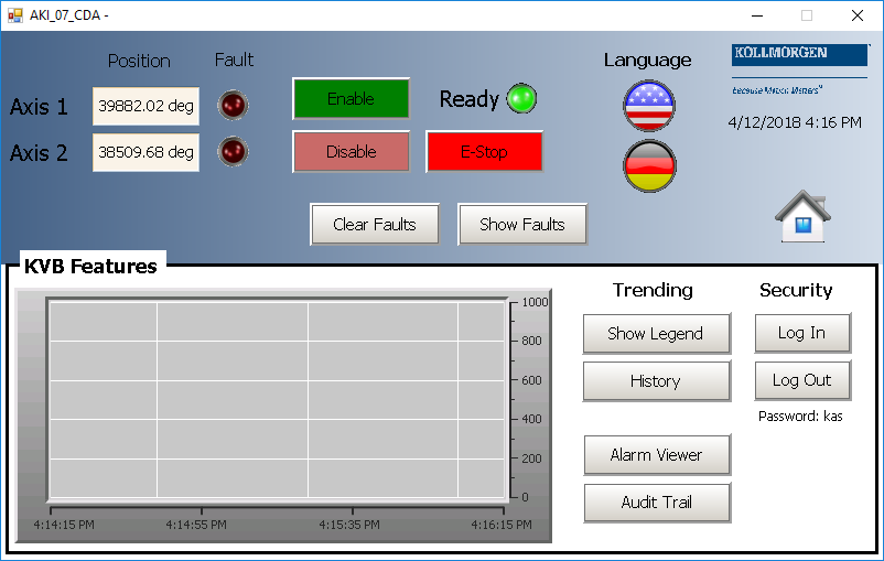
Included in the project template are HMI screens for the AKI terminals created in the KVB![]() Kollmorgen Visual Builder for HMI (Kollmorgen Visualization Builder) environment
Kollmorgen Visual Builder for HMI (Kollmorgen Visualization Builder) environment![]() Environment objects are global objects that exist before the execution of the script.
Typically, they are global objects of Astrolab that can be accessed from the script..
Environment objects are global objects that exist before the execution of the script.
Typically, they are global objects of Astrolab that can be accessed from the script..
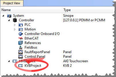
- The KVB software is a separate installation from the KAS-IDE Kollmorgen Automation Suite - Integrated Development Environment.
- In KAS-IDE, double-click the KVB Project item in the project tree to open KVB.
The project can be run in the KVB programming environment after the KAS-IDE program has started running.
Click on the Run button in the Project ribbon to start the program.
These screens, localized in English and German, are included that duplicate the controls on the IDE Internal Control panel screens.